This will be my 6th thin slumped meniscus mirror: prior mirrors include two 30x5/8 inch [760x16mm] f2.7, a 25x1/2 inch [635x13mm] f2.6, a 10.5x3/4 inch [267x19mm] f2.7 and a 13.2x1 inch [335x25mm] f3.0.
Goal: purchase and characterize the glass
An optical engineer making a multi-blank buy from DOTI offered me a chance to get in on the purchase.
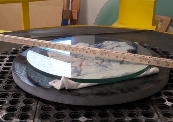
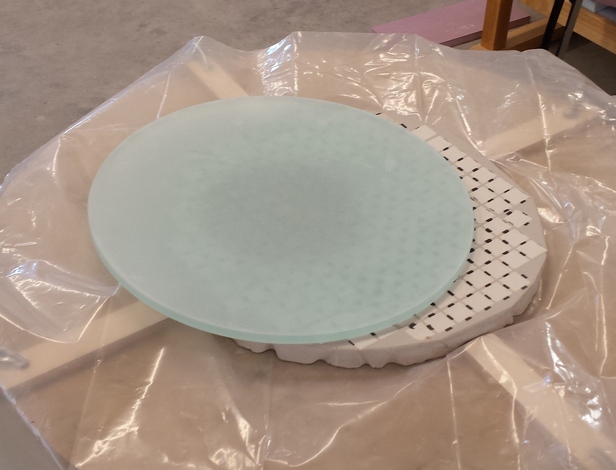
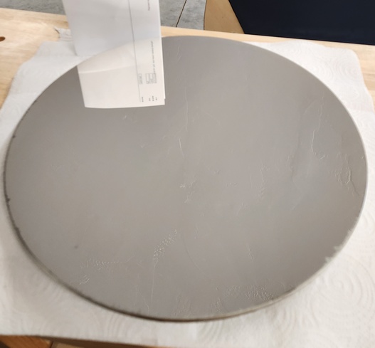
The mirror is a slumped and annealed meniscus plate glass blank of 16.25x0.5 inch [410x13mm] that weighs 9 lbs [4kg]. I can feel a low center and high 50% zone with my fingers; subsequent grinding reveals ~0.05 inch [1mm] saddle. I measure sagitta at 0.387 inches [98mm] which is a F/2.6.
![]()
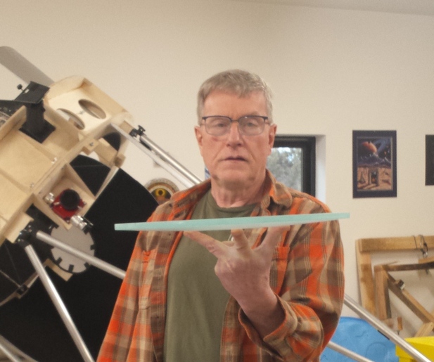
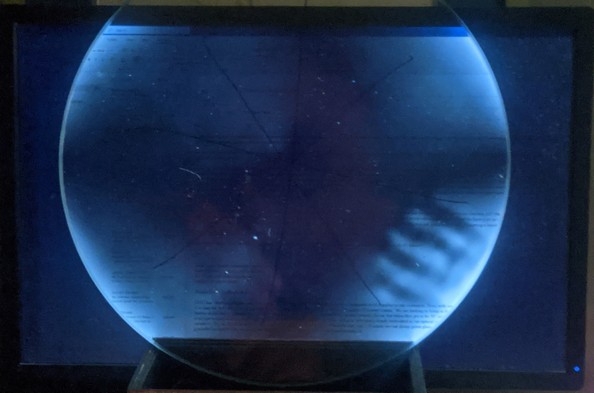
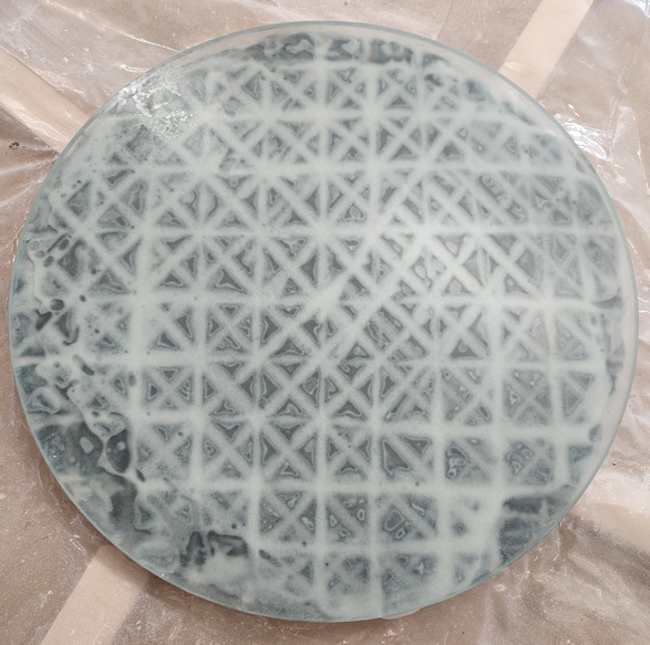
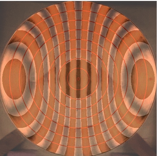
Polarization test by Rob Brown. The pattern shows mild strain, accentuated by the camera. You can see birefringence stress induced by the two-point edge contacts where the glass meets the wooden box. Simply grabbing the mirror for a couple seconds leaves a heavy hand print in crossed polarized light. This mirror parabolized beautifully and has a surprisingly stable star test as the cooling night wears on.
Goal: the goal of fine grinding is to make the backside and frontside spherical, then refine the surfaces with increasingly smaller grits, ending with lapping powder, ready for polishing.
I have been grinding the backside to a regular shape for many years but have never seen a demonstration as dramatic as that by Rob Brown, who found that grinding the backside regular on his matching 16.25 inch mirror caused the frontside's astigmatism to disappear and that a simpler mirror cell could be used. After grinding the backside regular on my blank, I measured the saddle at 0.004 inches [0.1mm], a small amount indeed. Check out Rob Brown's log and look for the Feb 17, 2022 and Feb 22-23, 2022 entries.
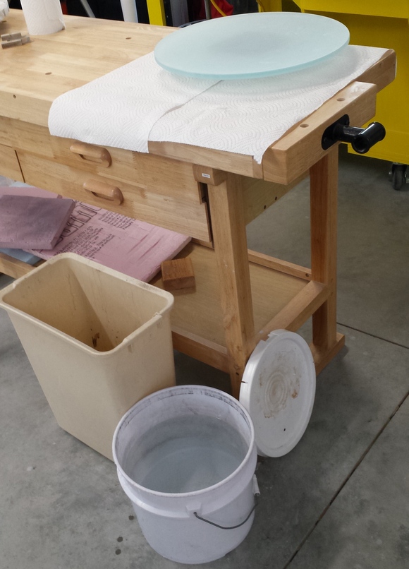
Grinding stand setup for grinding mirror backside showing mirror on top of tool.
Grinding stand setup for grinding mirror frontside showing from bottom to top: backside grinding tool, kitchen mat to smooth out contact, mirror, and finally tool on top.
Wash bucket for hands - I don't put left over silicon carbide down the sink.
Standard strokes are 1/3 diameter long = 5.3 inches, long strokes are 1/2 diameter long = 8 inches, short strokes are 1/4 diameter long = 4 inches. Long strokes flatten the lower piece, short strokes grind more evenly.
MOT = mirror on top; TOT = tool on top.
I use a sequence of grit sizes where each subsequent grit size is about half the preceding size. I start with sharp edged silicon carbide that gouges and tears out the glass, followed by plate shaped aluminum oxide that planes the glass; the silicon carbide fractures glass about three times as deeply as the aluminum oxide. I switch over to the aluminum oxide at about the same size as the final silicon carbide. I add a drop of soap to the spray bottle that facilitates grit distribution and wetting.
For each silicon carbide grit size, I grind the back then the front of the mirror, ensuring that any saddle shaped influence from the opposite side is minimized.
After 1.5 hrs grinding backside MOT (came into contact quickly starting with high center, very little saddle); mirror thickness varies from 0.475 inches to 0.480 inches; mirror lost 1/4 lb of weight.
After start of rough grinding mirror face: center is low - hardly has any grinding action after 3 hrs rough grinding mirror face TOT. Moving on to the next grit.
2 hrs backside grinding 120 grit MOT; took 15 min to come into contact; needed short strokes to bring center into contact; mirror thick=0.43 inches
2 hrs frontside grinding 120 grit TOT
2 hrs backside grinding 220 grit MOT; mirror thick=0.42 inches
2 hrs frontside grinding 220 grit TOT. Had to open up the channels in the tool. Some pits remain in center no doubt due to long strokes to lengthen the focal ratio; will serve as a marker for completion of next grit size.
1 hr backside grinding 500 grit MOT
3 hrs frontside grinding 500 grit TOT. Marked frontside pits with permanent marker: the ink disappears when the pit is ground through. After 2 hrs marked pits gone but a few anomalously larger pits remain in the center. Important that all silicon carbide pits be gone when finished with the last silicon carbide grit.
3 hrs frontside grinding 20 micron aluminum oxide TOT. A couple of scratches and pits at the 3 hr mark. Changed grinding method to one I've used before to prevent scratches on larger mirrors when tool is heavy and can stick at the beginning of a wet: use MOT with short oval strokes instead.
1/2 hr frontside grinding 20 micron aluminum oxide MOT short strokes. Scratches reduced to shadows after 15 min, gone after 30 min.
3 hrs frontside grinding 9 micron aluminum oxide TOT short oval strokes. An audible scritch occurred at the 1 hr mark: a contaminant was dragged in from the edge of the tool as the mirror was pushed back across - the scratch starts 2 inches in from the edge and is deepest there (strokes were +-2 inches), then tapers to the edge; after additional 1/2 hr parts of the scratch are disappearing. More 1/4 inch long scratches appearing at the 3 hr mark and the friction of movement is high; therefore abandoning this size and going up to the next largest size on hand.
1 hr frontside grinding 12 micron aluminum oxide TOT short oval strokes. Friction of movement much easier, coarser louder grinding action. A scratch at the 1/2 hr mark; clean surface at the 1 hr mark.
Grinding by hand took about 2 weeks. Clear aperture=16.2 inches; edge thick=0.40 inches; weight=7.5lbs
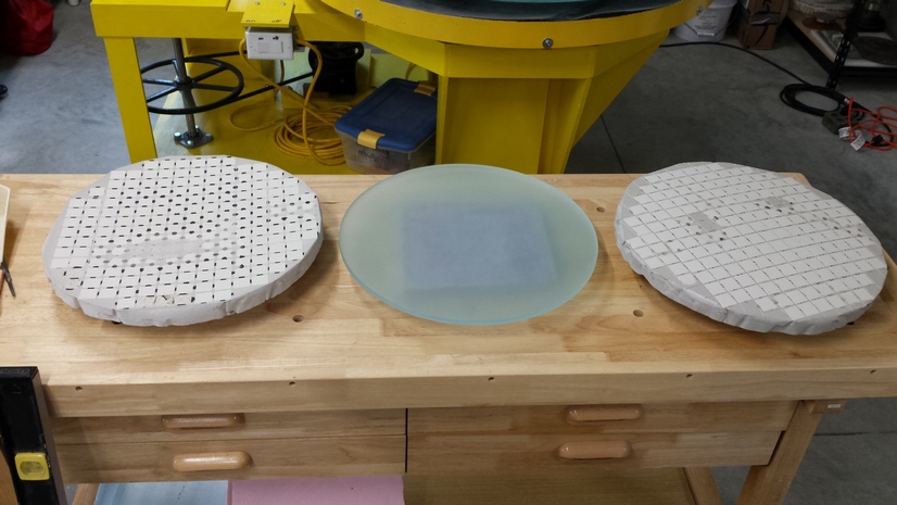
Grinding tools and mirror after fine grinding.
Goal: fully polish out the mirror with polishing pads with MOT.
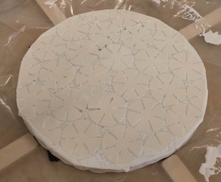
Polishing pads on tool. I heat the tool with a hot air gun to facilitate pads sticking hard.
Using polishing pads on a rigid tool is a low maintenance way to polish a mirror (no pitch lap to make, press and refresh).
28 hrs pad polishing MOT; clear aperture=16.25 inches, RoC (Radius of Curvature)=94 inches, FL=47 inches, FR=2.9.
I measured a starting FR of 2.6: I should have measured the sagitta across several diameters to detect the saddle shape that caused me to mis-measure the sagitta.
I use 1663 cerium oxide which is finer for a smoother polish but polishing slower. I used up my rough cerium oxide which goes several times faster but makes too rough of a surface for final parabolizing.
Thick cerium oxide to water mixture (1:1), run the pads as dry as possible: when pulled off the lap the mirror has a very thin layer of moisture that evaporates or can be wiped off with a single wipe.
During the first hour I picked up minor scratches and sleeks towards the edge mainly concentrated in one quadrant. Could be due to running the pads too dry, possibly contamination from the tool or from the environment. Other than the rare minor sleek, the minor scratches and sleeks have not re-occurred.
All of my pad polished mirrors always polish first in the center; considering that the pads are very much thicker than the aluminum oxide lapping powder, the tool + pads have a longer radius of curvature (flatter) than the mirror and therefore ought to polish the mirror's edge first: why is this not the case? The Ronchi bands are straight and the mirror's radius of curvature shrinks after the shine reaches the edge, showing that the mirror started spherical and flatter than the tool + pads.
After 1 hr enough shine to do a quick sanity Ronchi test that showed more polish in the center and not enough reflection at the edge; still, straight bands so good to go.
After 3 hrs the center is very shiny; the edge is barely shiny enough for the Ronchi test which shows straight bands and a modest TUE.
After 6 hrs the center casually to the eye looks finished; the edge is shiny, Ronchi image equally bright from center to edge; lots of sleeks remain.
After 14 hrs the laser pointer test shows that not a speck of haze remains at the edge; four minor scratches and sleeks faintly visible (also visible in the Ronchi test) in the same area; Ronchi test shows a long 70% zone with TUE.
After 28 hrs, double the time for the laser pointer test to past, three small scratches and sleeks, greatly diminished, remain. Visible in Ronchi test, hard to see on the surface. There is a good chance that they will disappear during pitch lap polishing.
Compare to the 13.2 inch [34cm] coming from 9 micron aluminum oxide polished out in 5 hrs with coarse cerium oxide by hand on an over-sized pitch lap and to the 25 inch coming from 20 micron aluminum oxide [64cm] polished out in 40 hrs with fine cerium oxide on polishing pads by machine. The difference in time is accounted for by the coarse cerium oxide being 2x to 4x faster and my polishing machine being 2x slower than by hand.
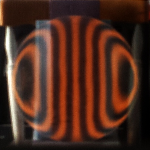
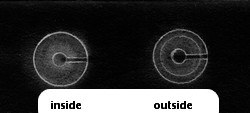
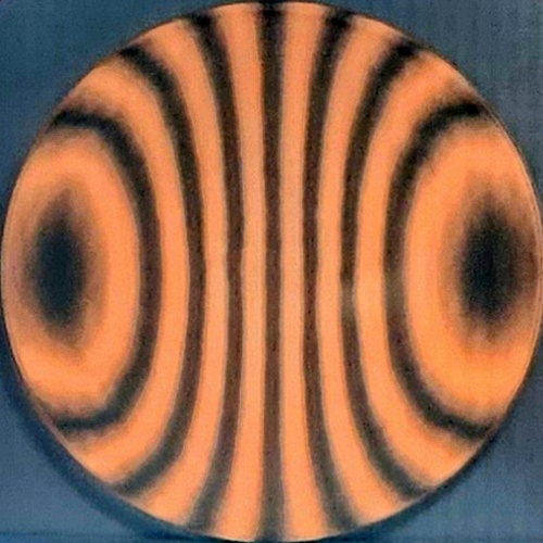
Here is a Ronchigram (inside RoC) from near the end of pad polishing on the rigid tool, showing no astigmatism but a turned up edge (TUE). The mirror is supported at a single point on its bottom edge and a single point on its middle backside. You can see some squeeze deformation at the mirror's very bottom arising from the single support point.
Initial polishing with pads took a couple of weeks. No astigmatism though three small scratches and sleeks remain that I expect to largely be removed by pitch lap polishing and parabolizing.
Goal: using pitch, polish the mirror to satisfy Danjon-Couder's two conditions: 1) a smooth surface, 2) deviates from best-fit parabola by a small fraction of a wavelength of light.
Ronchigram bands curve slightly differently than the very top of the Ronchigram, showing deformation from resting on a single point. The deformation is less than what I experienced with the 25 inch [64cm] f2.6, consistent with my prediction based on R^4/e^2. See my discussion and table.
Here is what the pitch lap looks like initially. I am using Gugolz 55 pitch with 1663 Super Cerox. The pitch is 3/8 inch [10mm] thick - as thick as the mirror! I like smaller polishing contact areas: I get lots of polishing action and the pitch conforms to the mirror's shape much better.
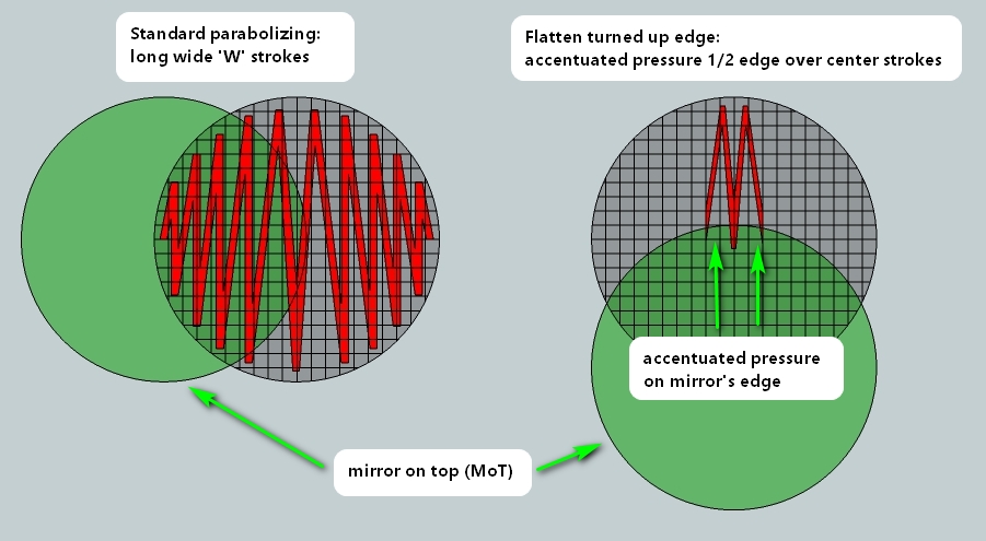
I use long wide strokes to parabolize. To tame the turned up edge I use accentuated pressure on the mirror's extreme edge with mirror edge starting at tool center to tool edge strokes.
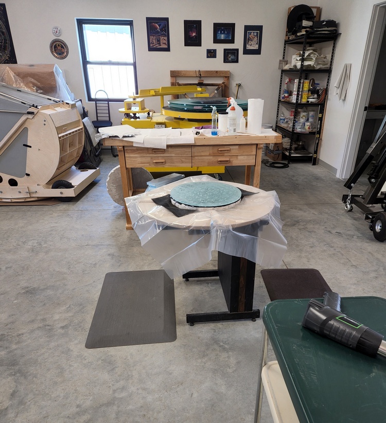
I work the mirror entirely by hand, 'walking the barrel'. Here is my work station. The hot air gun that I use to soften and shape the pitch is in the foreground with the grinding machine for large work in the background. Note the 20 inch and two 42 inch slumped thin blanks on the machine. The 30 inch f2.7 is to the left.
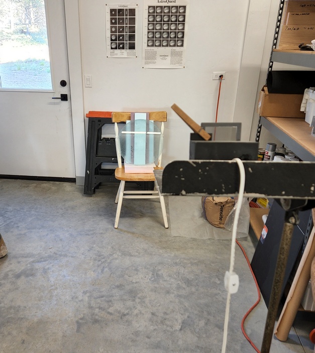
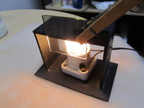
My testing setup, at least at this stage, is a Ronchi tester sitting on a music stand aimed downward at the mirror that sits on rigid foam insulation on a chair.
Just like my other thin meniscus blanks, this blank when heated shortens its radius of curvature and adds correction.
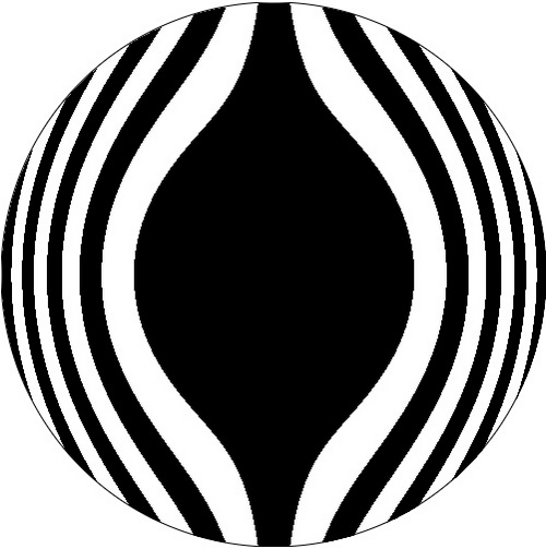
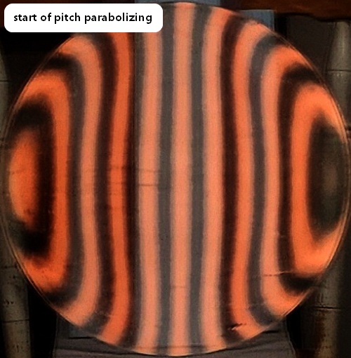
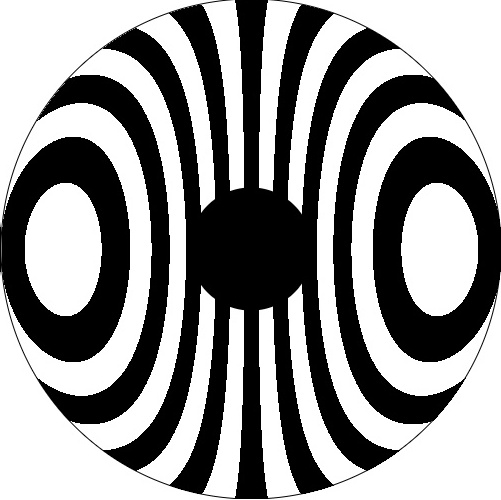
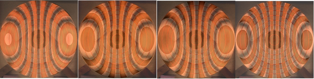
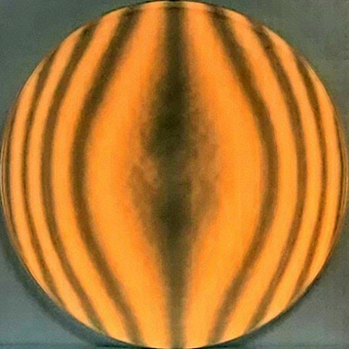
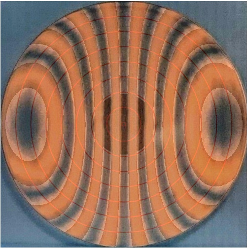
Stage 1: Ronchigrams inside RoC (note the turned up edge to start), starting with the ideal Ronchi pattern to match.
Radius of curvature (RoC) measures 93.6 inches, so focal length is 46.8 inches and focal ratio is f2.88 across the 16.25 inches clear aperture. Likely the RoC will shrink by half an inch during parabolization. Weight is 7.5 pounds.
Failed experiment: near the end I placed a 20 pound [9kg] on the mirror's back center. One time around the barrel caused major roughness that will take time to smooth out.
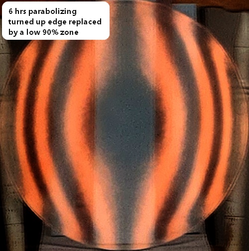
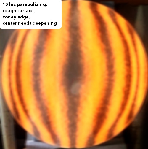
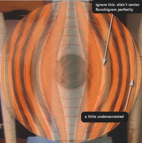
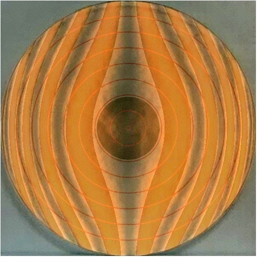
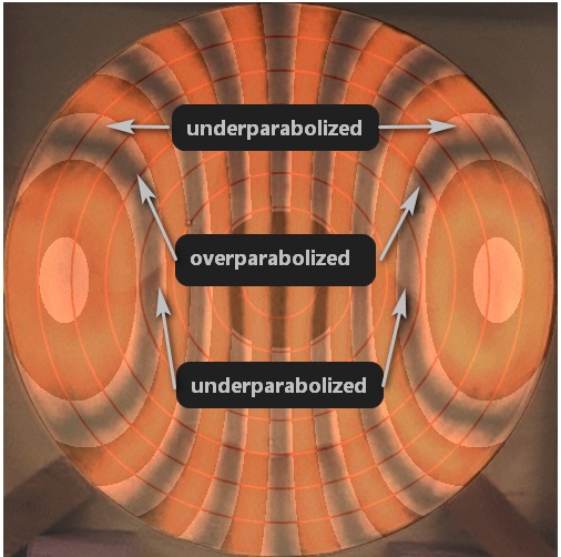
Stage 2: Ronchigrams outside RoC. Ending Ronchigram from above and the starting point for stage 2 shows a zony edge, a rough surface and the center needing a bit more deepening. All these issues will be fixed. Time to move on to exact Ronchigram Matching with the grating outside of the radius of curvature. I am using the wide 'W' stroke I mention above.
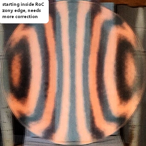
Not as bad as I feared for the first Ronchi Match attempt. The edge suffers from the kink left over from the turned up edge (the zone where the edge began to turn up leaves a low zone as the edge is flattened). Another way to look at the situation is to say that the 70% zone is low with respect to the center and extreme edge. The next section on slopes and how I fix a low 70% zone is copied from my 30 inch mirror log.
The mirror's surface is curved with varying slopes that direct the parallel light from afar to a point of focus. Tests like the Foucault and Ronchi are slope tests: they measure slope. Tests like the Bath Interferometer measure Optical Path Difference to derive the mirror's surface profile. Slopes can be calculated from the mirror's surface profile. While slopes can be strung together to calculate the mirror profile, they are not the mirror's surface. Thinking in slopes and testing directly with slopes is very useful when considering how to bring light together to form a nice tight star image or a nice sharp planetary image (as long as we understand that the tightly focused light forms an Airy Disk with rings due to diffraction - our goal is to form a perfect Airy Disk and rings). Here is how I think about slopes and deal with, in this case, a low 70% zone.
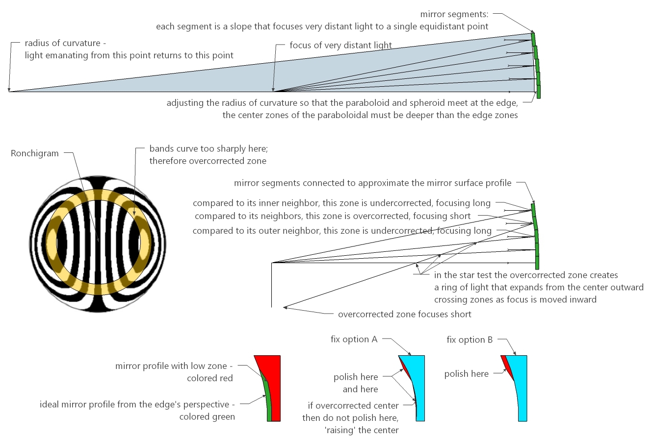
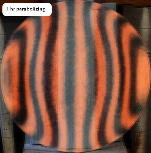
Five hours to flatten the edge using the 2nd stroke pattern illustrated earlier! And the parabolization disappeared too. The zone just inside the turned up edge became a low zone thanks to the parabolization effort then a turned down edge. Better to have fixed the turned up edge before any parabolization - do one thing at a time.
The edge zones are developing zones.
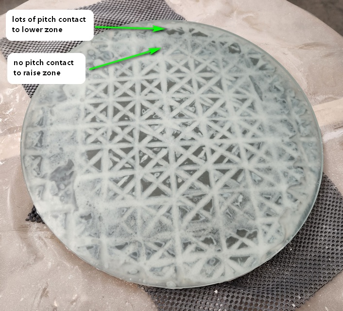
Here is the pitch lap configuration to raise the 80% zone and lower the 90% zone. I normally do not chase zones because it often leads to more zones and takes me away from my standard parabolizing process. Here it is justified because the zone is persisting over many sessions.
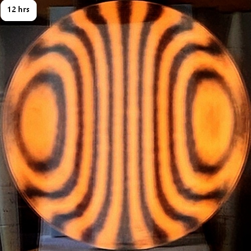
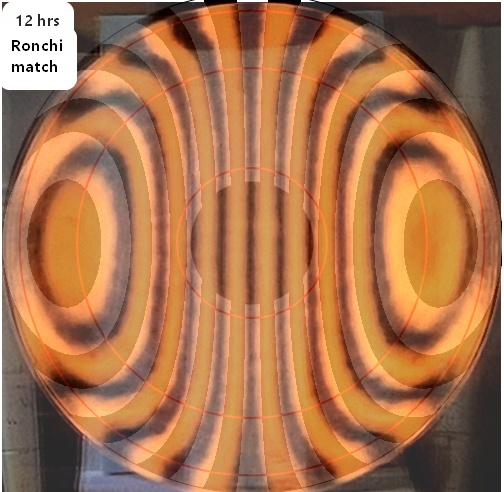
After a few minutes with the pitch lap configured as above (time spent is 3 1/2 hrs for this second parabolization try, along with 12 hrs for the first parabolizing try and 5 hrs previously to flatten the edge; total time is 20 1/2 hrs), I am close enough for my first Matching Ronchi.
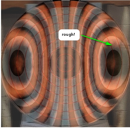
The surface is incredibly rough. The Gugolz #55 pitch is acting hard and brittle (shop temp is 60F), even scritching at times (luckily no sleeks). After only two times around the barrel the mirror is rocking back and forth on the pitch lap. This is due to the changing mirror shape (not only increasing parabolization but also a changing RoC caused by polishing friction heating the mirror's face). The pitch is not keeping up with the mirror's changes.
The roughness is decreasing and the Ronchi bands are becoming smoother after a few minutes of slow strokes with lessoned pressure. I also warmed the shop to 64F and rechanneled the lap. The outer inch needs much more correction.
After four more sessions of twice around the stand each, continuing with the lap configured as above. The overall correction is close but there seems to be roughness near the edge.

Here are the last four sessions from most recent on the left showing how I've increased correction.
Time spent on parabolizing so far: 12 hrs for the first attempt while also trying to flatten the edge (the edge did not flatten by the time nearly full parabolization was reached); followed by 5 hrs flattening the edge (which resulted in a spherical mirror). Time spent so far on the second parabolizing attempt is 4 hrs. Total time parabolizing then is 12+5+4=21 hrs.
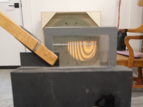
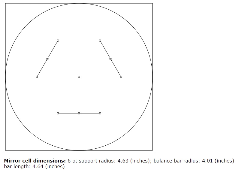
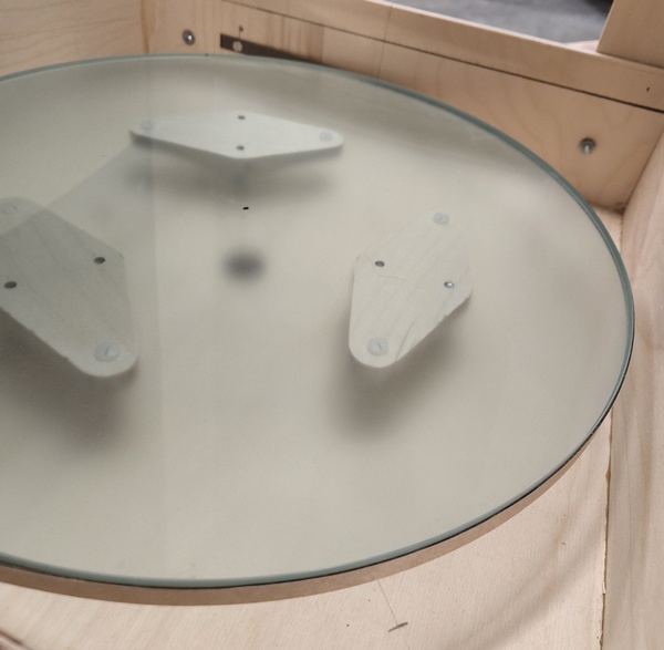
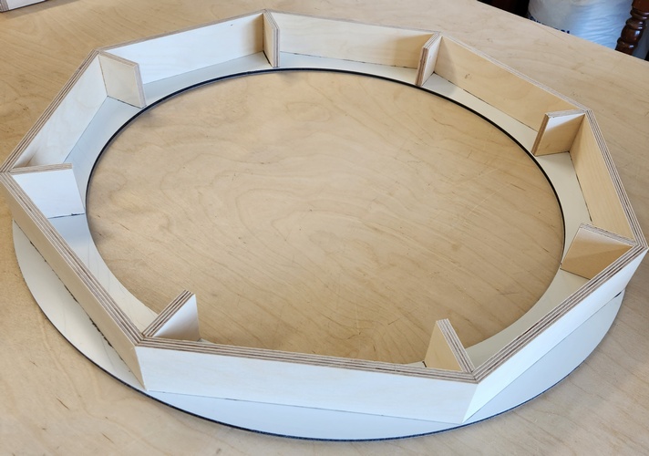
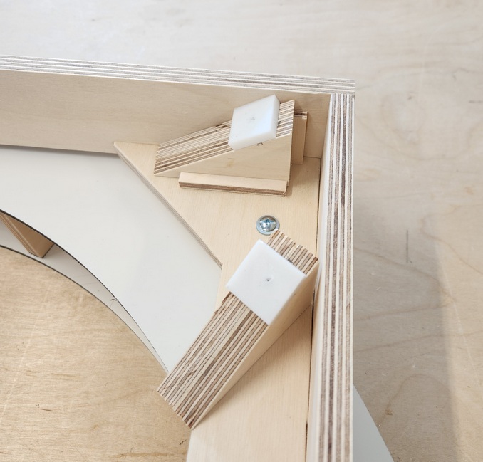
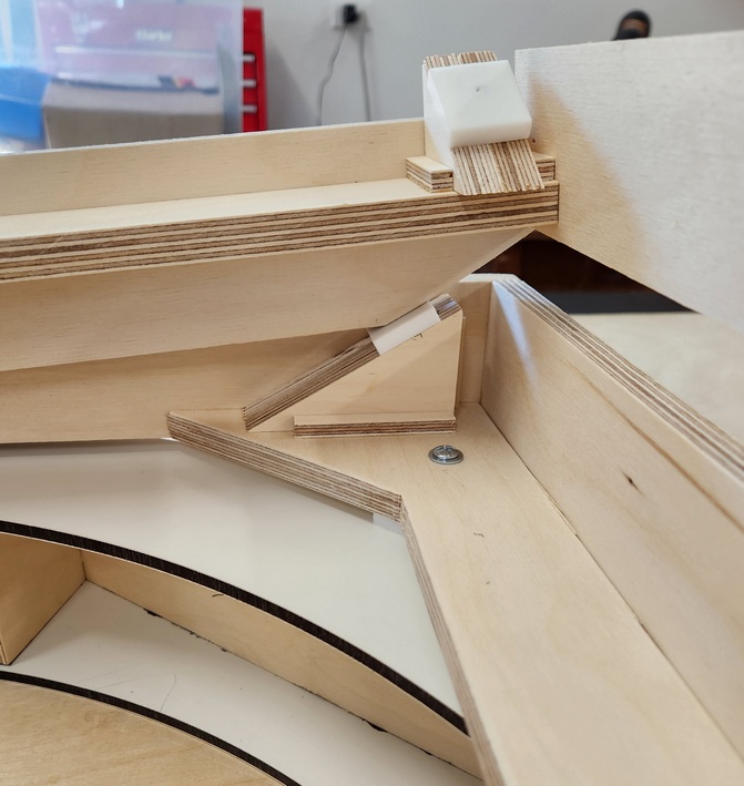
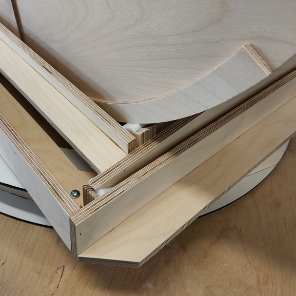
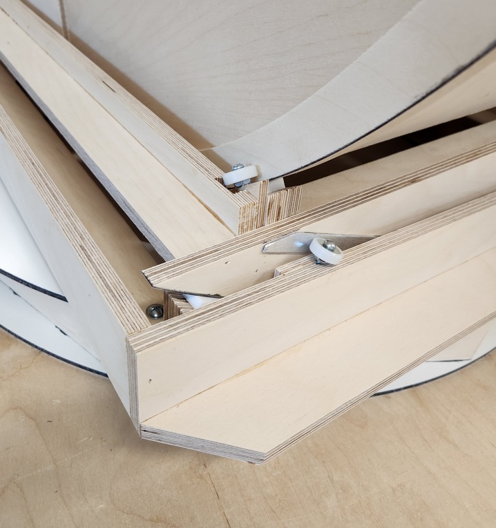
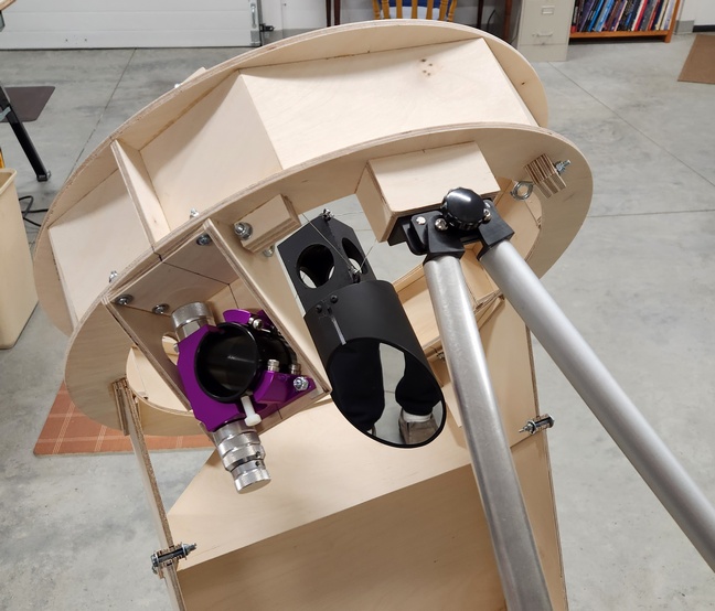
For accurate Ronchigrams, the mirror needs to be properly supported on the test stand. That means building the mirror cell. In this case, a six point back support flotation, dimensions from my telescope designer. Pictured is an experiment with 90 degree separated edge supports.
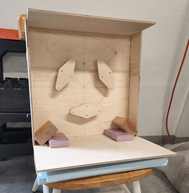
The mirror deforms some with the 90 degree separated edge supports though less than the 25 inch f2.6 and 30 inch f2.7 mirrors, consistent with the bending formula of mirror radius ^ 4th power / thickness squared. The mirror also deforms less then my larger mirrors when sitting on a single foam edge support and resting on its backside. Again, consistent with the bending formula.
Dimensions:
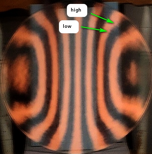
First star test result: not bad at all: Polaris focuses nicely to a crisp pinpoint (no stig) with decent diagonal breakout on both sides; however, that broad 90%-ish zone that I've been working deeper is still undercorrected - it needs more deepening yet. The zonal ring is not that bad because it does not intrude into the diagonal breakout as the star is focused smaller and smaller. Still, it is a zone. These fast mirrors are really touchy to zonal issues near the edge. They are small fractions of a wavelength yet they show in the star test. Focus is exactly where I calculated it to be.
I also incorporated an idea that I've been experimenting with for a long time: a thick diagonal support stalk (1.5 inches) which helps diagnose zones in the star test. Where the stalk appears thinner in the out of focus star image those mirror zones are closer to focus and where the stalk appears thicker those mirror zones are further from focus. If the stalk is too thin then it is hard to see; if the stalk is too thick then it is not sensitive.
This is my seventh F3 or faster mirror that I have successfully made using the Matching Ronchi test. This also shows that a 16.25 inch f2.9 mirror that is 0.4 inches thick can be ground, polished and parabolized. This further shows that such a thin mirror can be adequately supported on a 6 point back support (the temporary 2 pt edge support is iffy). I continue to use the star test to verify the Matching Ronchi and to ferret out minor zonal issues.
Final adjustments to the mirror using the star test makes a major impact on mirror performance and takes as long as any previous stage. A solid star test means a solid mirror satisfying the two Danjon-Couder mirror quality standards: 1) smooth and 2) total error a small fraction of a wavelength of light. A solid mirror performs as if it were perfect for deep-sky observations and for all but the most difficult planetary observing, where only an experienced observer given lots of time can barely distinguish the difference.
Parabolizing then star test session #1: 2x around the polishing stand (wide long wWw strokes); star test results: the high zone near the edge greatly reduced but the mirror overall is ever so slightly undercorrected now.
Parabolizing then star test session #2: 3x around the polishing stand (wide long wWw strokes); star test results: no change.
Parabolizing then star test session #3: 3x around the polishing stand (wide long wWw strokes); star test results: correction very good; the 80-90% zone is high/undercorrected. Using my Matching Ronchi calculator, the error is on the order of 1/5 wavefront, 1/10 wave on the mirror's surface (since the center is ever so slightly overcorrected, I judge the current wavefront rating ~ 1/4 wave).
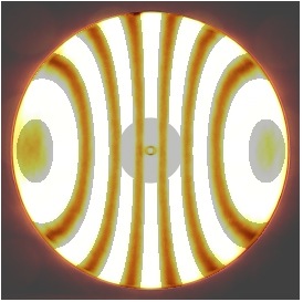
Matching Ronchis:
Parabolizing then star test session #4: 1x around the polishing stand with 1/3 center over center strokes on pitch lap configured for heavy contact at 80-90% zone, light contact elsewhere; A quick handwaving of the Ronchi tester shows that the bands near the edge are smoother and better proportioned, though not perfectly so; star test results: very close; the 80-90% zone shows as barely undercorrected (no corresponding shadow inside of focus meaning that the high zone has shrunk) with a hint of overall overcorrection.
Parabolizing then star test session #5: 1x around the polishing stand quickly with fewer and lighter strokes with lap and strokes as above; star test results: the 80-90% zone is perfect now along with the overall correction, but there is the slightest high zone at 60-70% now; will take a look with the Ronchi to verify location; since it is a high zone there is little chance of harm in continuing to improve the mirror. Looking at the Ronchi, the high zone is barely perceptible and located at the 70% zone.
Parabolizing then star test session #6: 1x around the polishing stand with very few strokes, slow and light on lap configured for most contact at 60-70% zone, some contact inward; star test results: the slightly high 60-70% zone is gone but in the very difficult conditions of gusting cold winds, there was a suggestion of overcorrection in the central zones and undercorrection in the outer zones. The Matching Ronchis look quite good.
Matching Ronchis:
Here's a MR (using a finer grating with more lines per linch) from my 13.2 inch F3.0 mirror figured by Ronchi then star test that gives a great star test result. The quality and style of the 16.25 inch's Matching Ronchi is very close to that of the 13.2 inch.
Parabolizing then star test session #7: 1x around the polishing stand with very few strokes, slow and light on lap configured for contact at 70-90% zone: star test looks smooth, no zones, a hint of overcorrection in the central zones (later found to be caused by the mirror cooling in the cold night air - a common issue with mirrors).
The mirror is finished.
I spent 4 1/2 hrs of polishing time on the second parabolizing attempt. Time spent in adjusting the pitch lap, pressing the mirror, testing and analyzing was considerably more. Looking back, I began working on this mirror a little more than four months ago. Most of the time was spent on the first parabolizing attempt, learning how to parabolize this particular mirror size on this particular pitch lap configuration.
By comparison I used 5 parabolizing then star test sessions for my 20.5 inch F4.8 2 1/8 inch thick mirror, a very fine mirror that on one night of perfect seeing I used 6000x magnification. I used about two dozen star test sessions for the 25 inch F2.6 9/16 inch thick meniscus mirror.
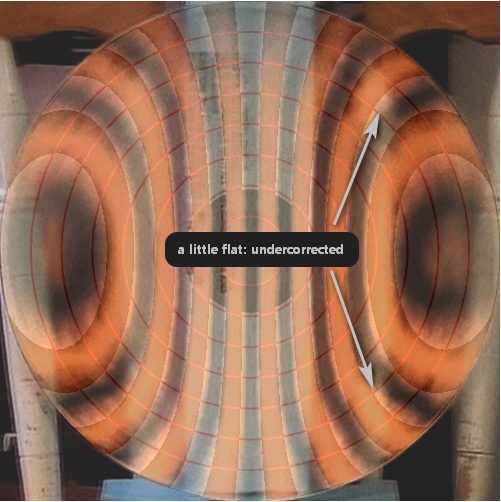
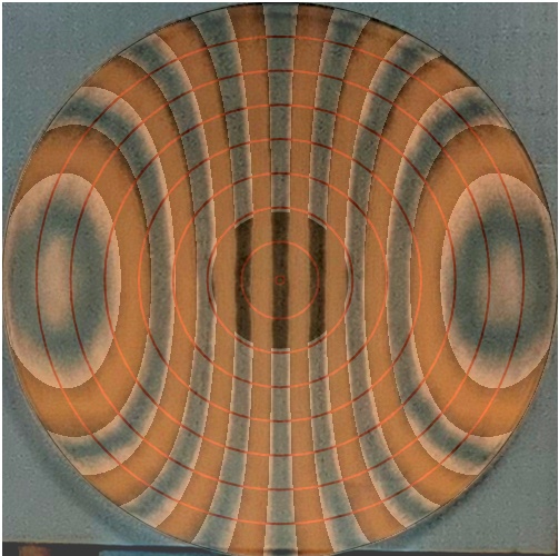
Final Ronchigrams (note that the vertical grating adds noise in the guise of vertical streaks coming off the bands):
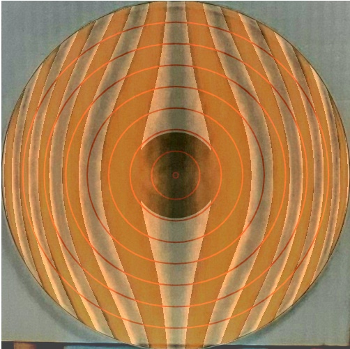
Another question is, "What has the seven star test based parabolizing sessions gotten me?" The answer is a smoother and better fitting paraboloid as shown by the Matching Ronchis made 'after' the star test sessions and 'before' the star test sessions began. This demonstrates that parabolizing by star testing works and that the results can be seen in the Matching Ronchigrams. On the left is the Matching Ronchi before star test parabolizing and on the right is the Matching Ronchi after finishing with star test parabolizing. The Ronchi bands fit much better and are smoother (ignore the vertical banding caused by the grating).
I added a passive vent to the mirror cell, knowing from experience that thin meniscus mirrors will overcorrect when moved from the warm shop to the cold night air unless the mirror is vented. This works as hoped: the star test shows perfect correction using the diagonal breakout test.
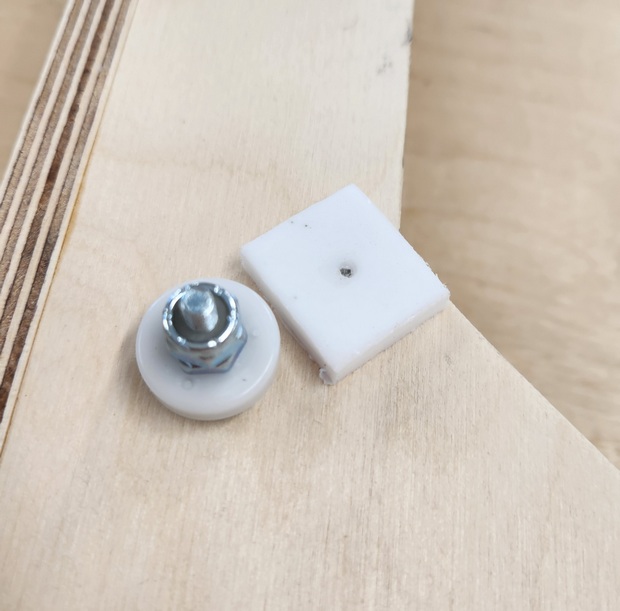
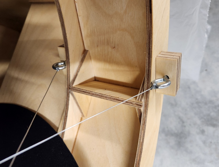
I also replaced the two edge supports at 90 degrees separation with a sling centered on the mirror's back edge, which is at its center of gravity. The slightly out of focus star test patterns are beautifully round at highest magnification. Before, I could see some distortion from the two point edge support at higher magnifications particularly when the mirror was not perfectly seated. The sling is a strip of Formica.
Here is the sling and passive vent.
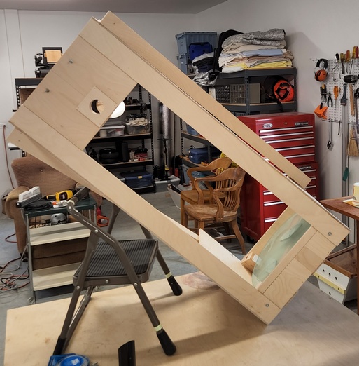
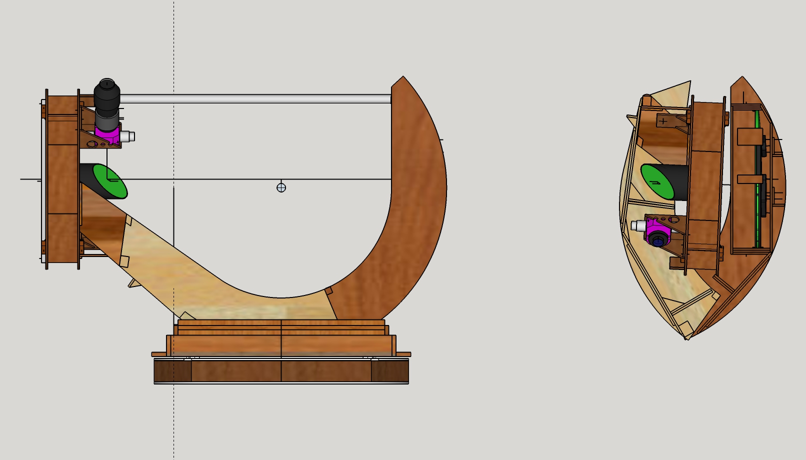
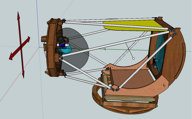
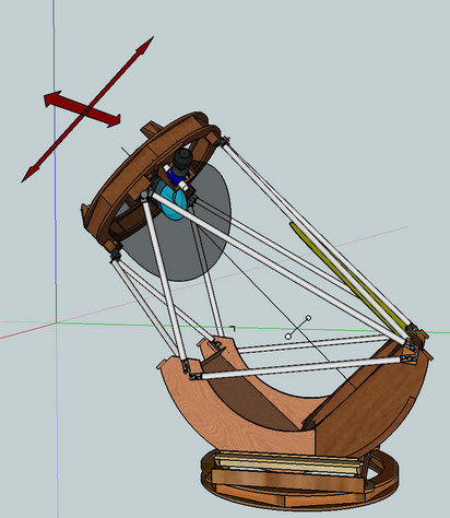
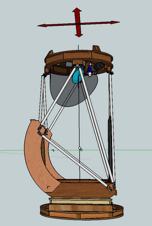
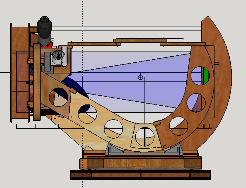
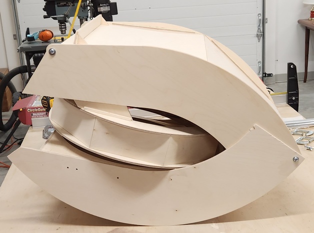
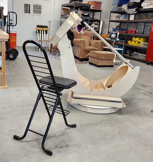
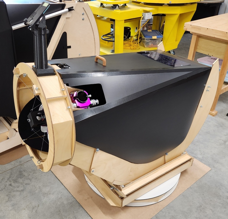
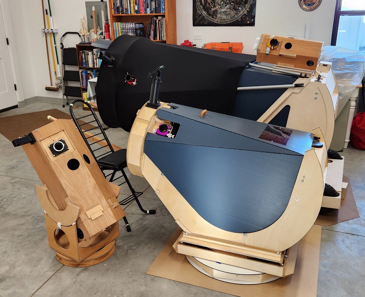
I considered several Optical Tube Assembly (OTA) designs.
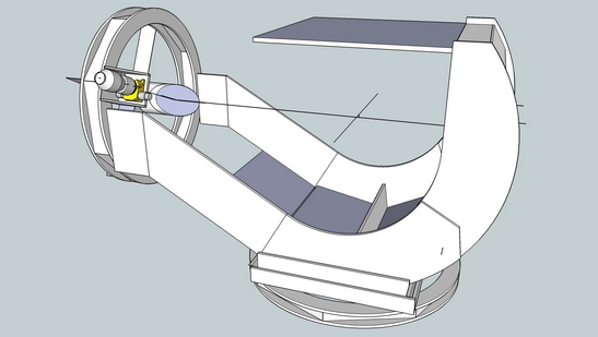
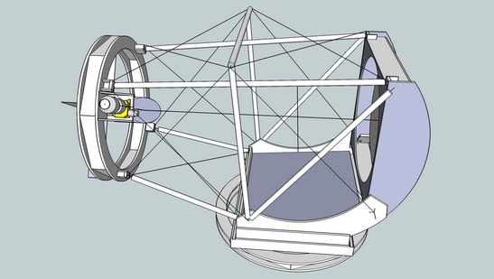
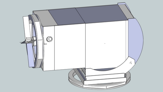
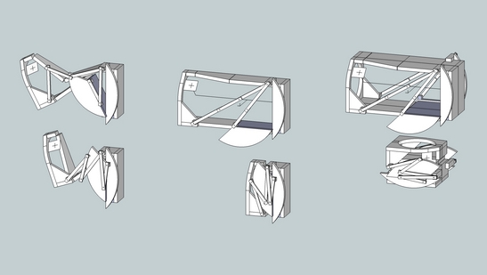
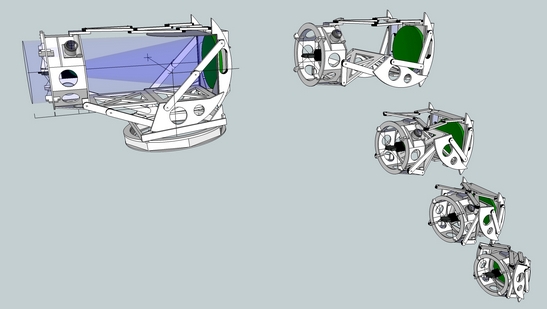
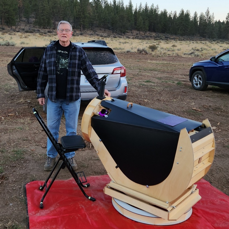
I choose the 'ZipDob' design which will fit a backseat of a car and weigh about 25 pounds [11kg]. The ZipDob in particular solves the Center of Gravity problem by using the sweeping altitude rims to connect the upper end to the mirror box, where the CG lies more in the middle of the tube assembly thanks to the lightweight mirror on one end and heavy eyepiece and coma corrector on the other end. The change in eyepiece height from horizontal to vertical is a scant 10 inches [25cm], varying from 36 to 46 inches [91 to 117cm], allowing me to use my observing chair for all orientations.
I will also give this telescope a 3-axis mounting. This is my third 3-axis mounted telescope, following the 25 inch and 30 inch telescopes. The 3-axis mounting, implemented via a dual flex-rocker, gives the telescope a natural movement: altitude-azimuth near the horizon transitioning to an altitude-altitude movement near the zenith. The 3-axis mounting also allows the eyepiece to be lifted and lowered as desired. Here are drawings of the 25 inch transitioning from horizontal to vertical.
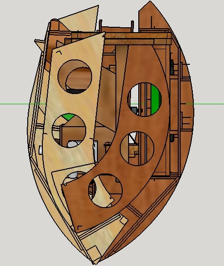
This will be my third 'ZipDob', the first two being iterations of the 13.2 inch [34cm] f3.0.
A comparison of the 2nd ZipDob design with the 16.25 inch design.
I align the focuser during construction of the upper end so that the laser collimator hits the target across the ring. This helps greatly with centering the diagonal under the focuser. I first used this construction technique while building my 30 inch f2.7, finding it a major help aligning the optics.
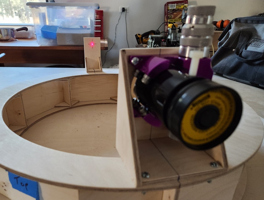
There are no collimation adjustments on the secondary. The scope is built aligned with a jig. The primary is aligned during initial assembly. I've never had to re-touch the collimation in three years of use. Adjustments are usually poorly designed and pernicious. They work loose, particularly the diagonal adjustments. The key is to remove the adjustments and build it 'right' the first time, using jigs and lasers to align.
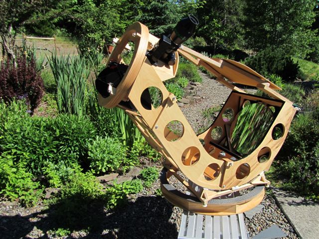
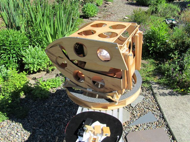
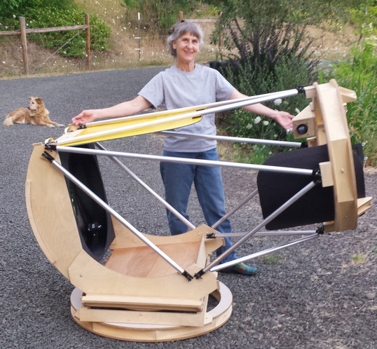
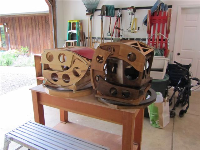
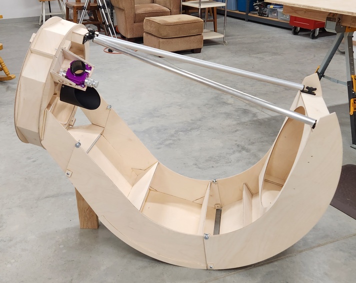
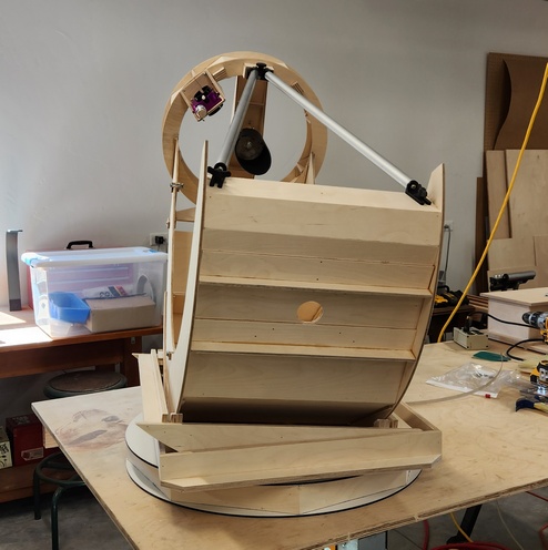
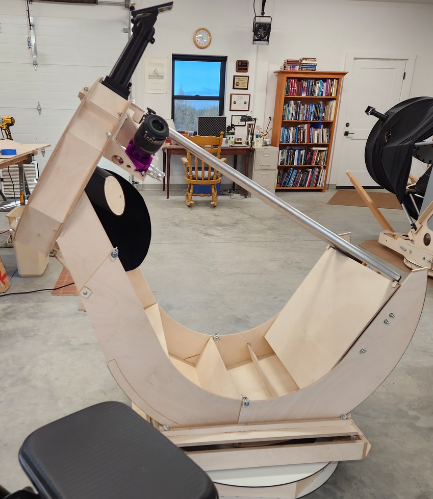
First trial fitting of the ZipDob16.
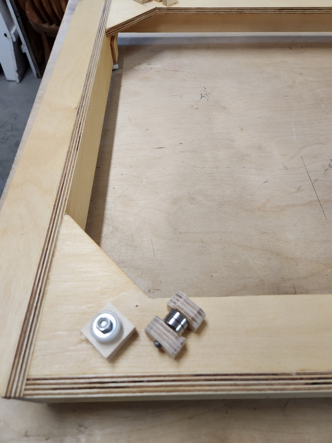
Base ring made from Alucobond and half inch Baltic Birch under construction. The top layer of Alucobond remains to be glued on with JB-Weld. This base ring is taller than the 30 inch base because I want to bring the eyepiece height up.
Like the 30 inch design, I use replaceable bearing blocks so that I can adjust after the build for the smoothest motion at high magnification. For example, on the 30 inch I made Teflon, Nylon and ball bearing blocks, ending up with some ball bearing and some Teflon blocks for smoothest motion. I could even make seesaw bearings composed of a combination of a ball bearing and a Teflon block, reducing friction by the ratio of the seesaw arms.
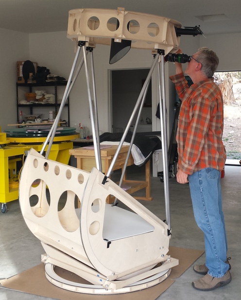
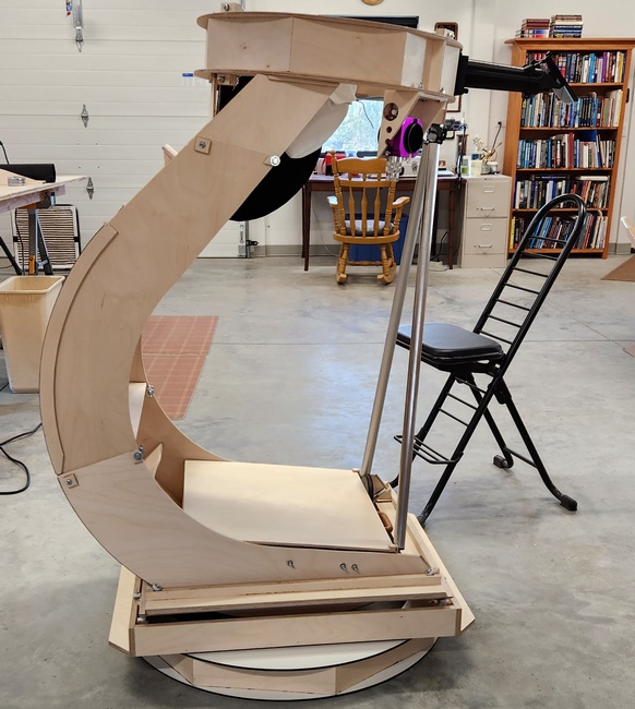
First assembly images showing the az bearing and keeper, the alt-alt bearings, the alt-alt bearing keepers, the 2nd alt axis tipped demonstrating the change in eyepiece angle and the observing chair next to the scope.
I eventually replaced the azimuth's Teflon on Alucobond bearings with small ball bearings, using the natural friction of the bearings and side keepers.
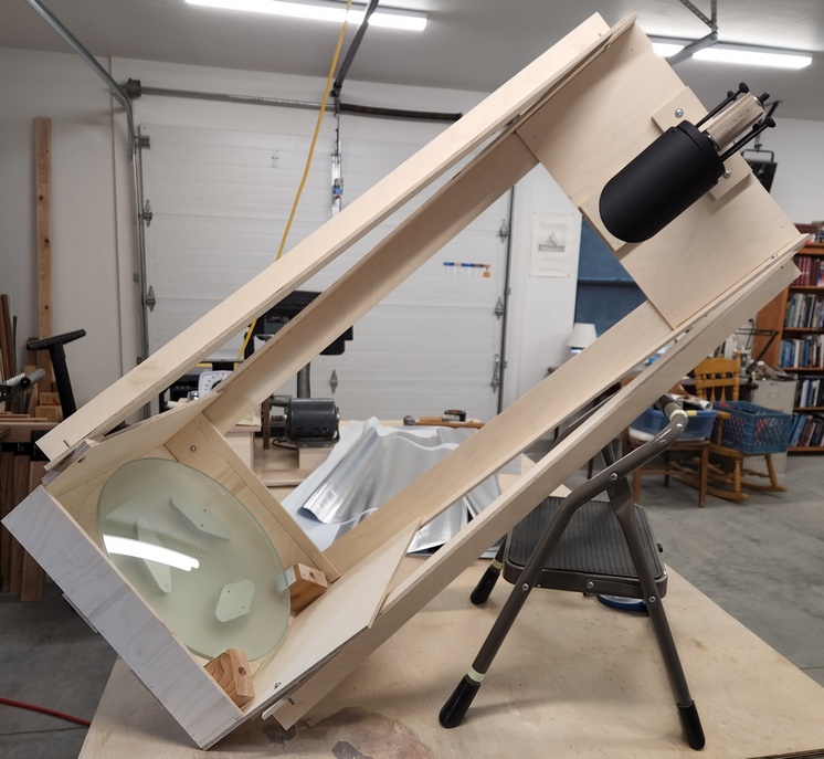
I assembled the optics last night. The focuser and diagonal are perfectly aligned! The laser collimation dot hits the exact center of the mirror. Focuser alignment is built in during assembly using a target. Diagonal alignment is built in using a diagonal jig. Eh, the primary return was not perfect - could not think how I would build a jig for the mirror box since the scope was not built.
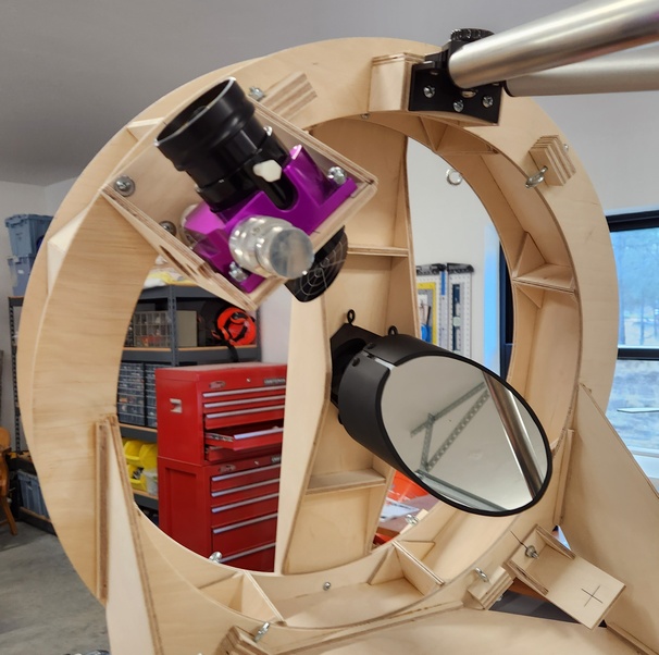
A quick star test shows that the telescope focuses exactly as designed. I like 3/8 inch [10mm] in-travel for the focuser.
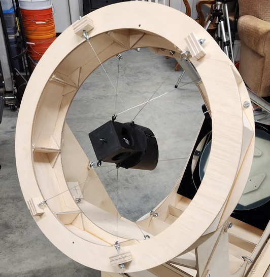
The 22 gauge wire spider is solid: absolutely not a smidgeon of change in the laser collimator's aim on the primary from horizontal to vertical. There is a small fraction-of-a-second one time shake when the upper end is rapped hard by my knuckles. I use the diagonal shroud and the base, gluing in a 1/2 inch bolt with JB-Weld. This so that the base can rotate with respect to the diagonal holder's frame. The wires are at 90 degrees angle, so the small mounting blocks on the upper end are closer together at the top and the bottom.
Finder and diagonal baffling installed. I added a two pound [1kg] counterweight on the far top mirror box. Sitting in the observing chair I can easily look into the eyepiece from scope pointing horizontal to scope pointing vertical - nice! Weight of the scope is 25 pounds [11kg] not counting eyepiece and not counting the base. Only silvering the primary mirror and shrouding remain.
In order to obviate Dobson's hole, the scope is designed to push past vertical in both alt-alt axes.
I built a rigid shroud from sign board lined with felt which unfurls. I later replaced it with Protostar's flockboard which does not warp in the hot Sun. This looks good and promises to work nicely.
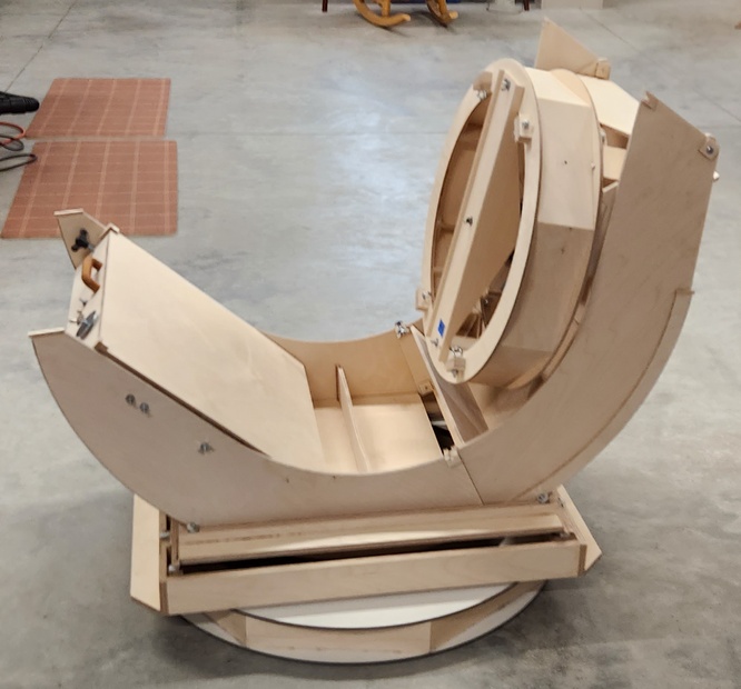
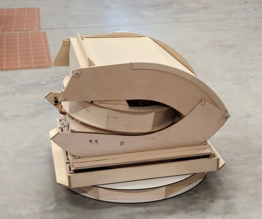
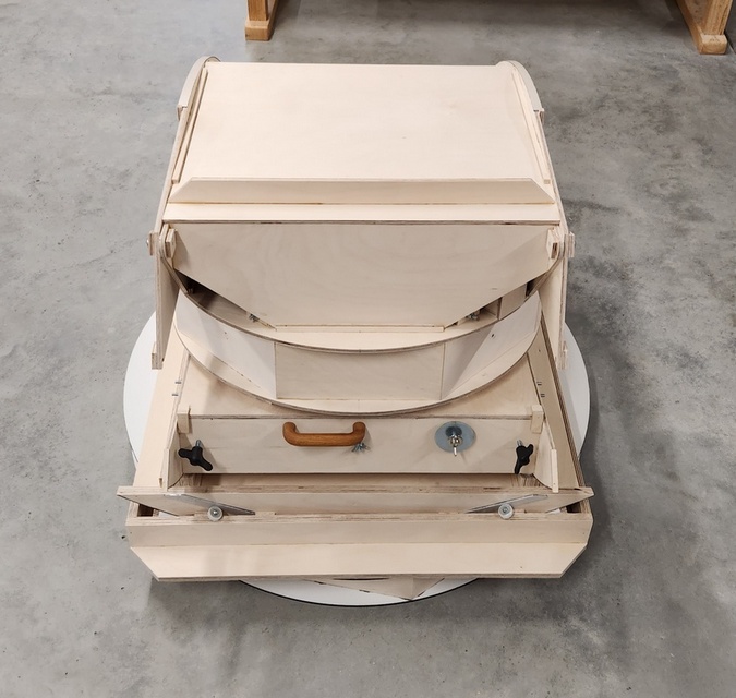
The scope folds up for compact transport. Here is an image of the first fold followed by two images of the final fold. The final fold size is approximately 20x32x20 inches [51x81x51cm] compared to a size of 16x24x18 inches [41x61x46cm] for the 13.2 inch [34cm] ZipDob II (not counting the double flex rockers and the base ring). Counting the rockers and base ring, the size is 24x32x31 inches [61x81x76cm]. The scope at 25 pounds [11kg] (not counting the rockers and base) is surprisingly easy to carry around.
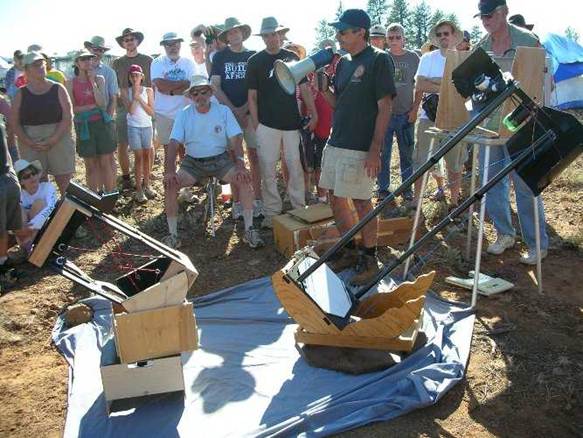
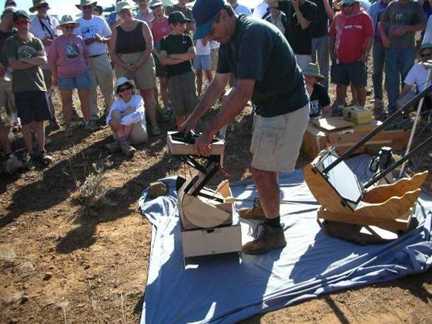
And an image of the 16 inch next to the 30/6 inch combo scope and the 10 inch.
I silvered the mirror following the Oregon Scope Werks silvering process. I reused the silvering jig that I built for the 30 inch. The coating itself is spectacular though the edge is ragged in spots. The ragged edge could mean that the edge needed more cleaning despite the 45 minutes spent cleaning; could also mean that the mirror's extreme edge tended to dry out before I applied the sensitizer. Since the coating is so good I will not redo it in hopes of making the edge better, particularly since I am not sure of the cause of the ragged spots at the edge.
I find it very satisfying to make the mirror and apply my own reflective coating.
I center dot using a permanent marker pen with a jig. I find it easier to accurately aim the laser collimator beam at the black spot than inside a notebook ring.

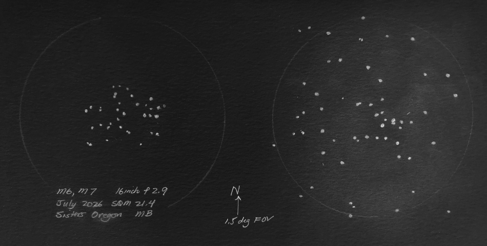
Jupiter's sharp - can see white Europa transiting. The field is a little hazy but then Jupiter looks a little hazy in the sky. M31 is full of detail and extends on and on; lots of faint galactic cirrus that I will study on a better night. Orion Neb is fantastic! Faint nebulosity extending everywhere for degrees. Color. The Trapezium is so sharp and contrasty. Caroline's Rose is beautiful: dark lanes and star colors, though fainter and more muted than in the 30 inch. IFN surround M33 and extend everywhere.
Using the observing chair for all orientations, not even needing to change the seat's setting is nice.
The star test started a hint undercorrected with a hint of a triangle shape but quickly became round and good. The rigid shroud protected the mirror's figure and silver coating in that the star test stayed good throughout the hour of observing. I used no fan and kept the vent in the back of the mirror box covered.
The scope is light enough at 25 pounds, though it was a little awkward to carry the scope the 75 feet to my observing spot. The scope is hinting at stuff I haven't seen before and carries the promise of much more.
Later I observed Comet 2022 E3 ZTF at 300x as soon as I had carried the scope out. Nice and sharp star images.
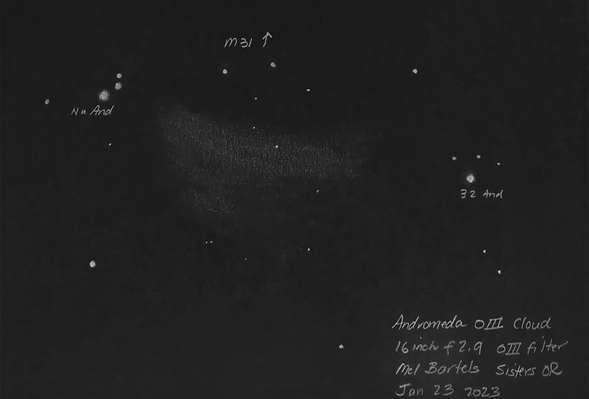
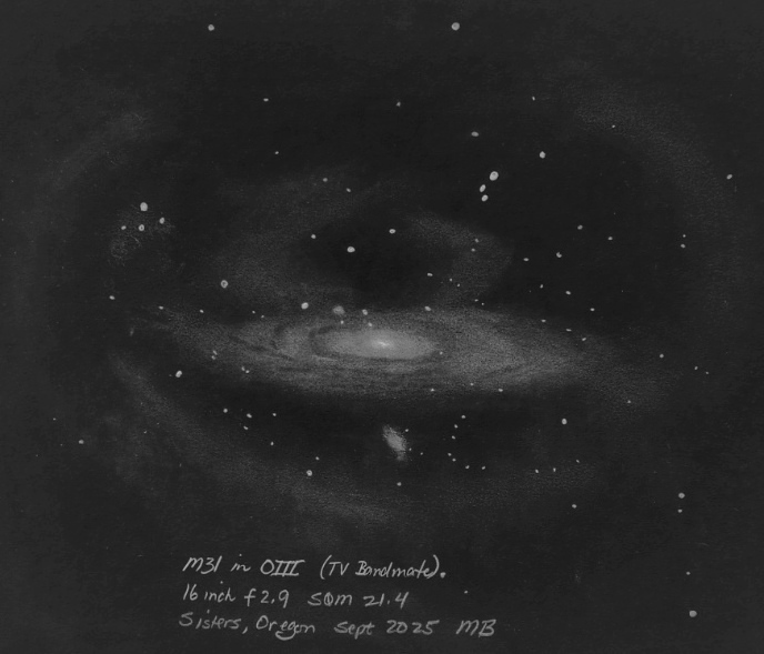
The newly discovered OIII cloud next to M31 is readily seen. A perfect fit for the wide angle view.
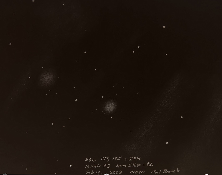
M31's satellite galaxies: NGC 147 and NGC 185 with IFN.
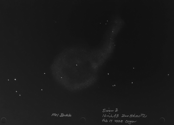
Sivan 2.
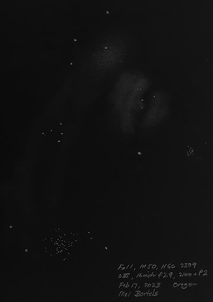
Fal1 OIII cloud.
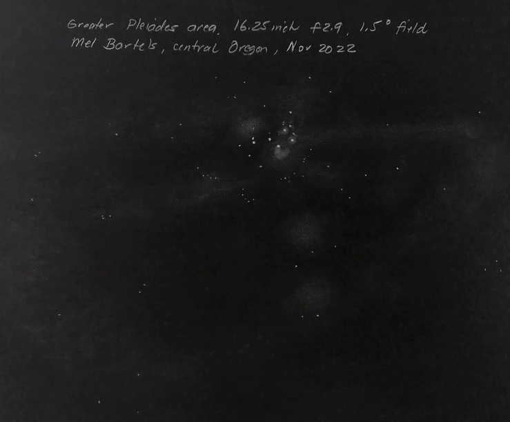
Pleiades super wide angle.
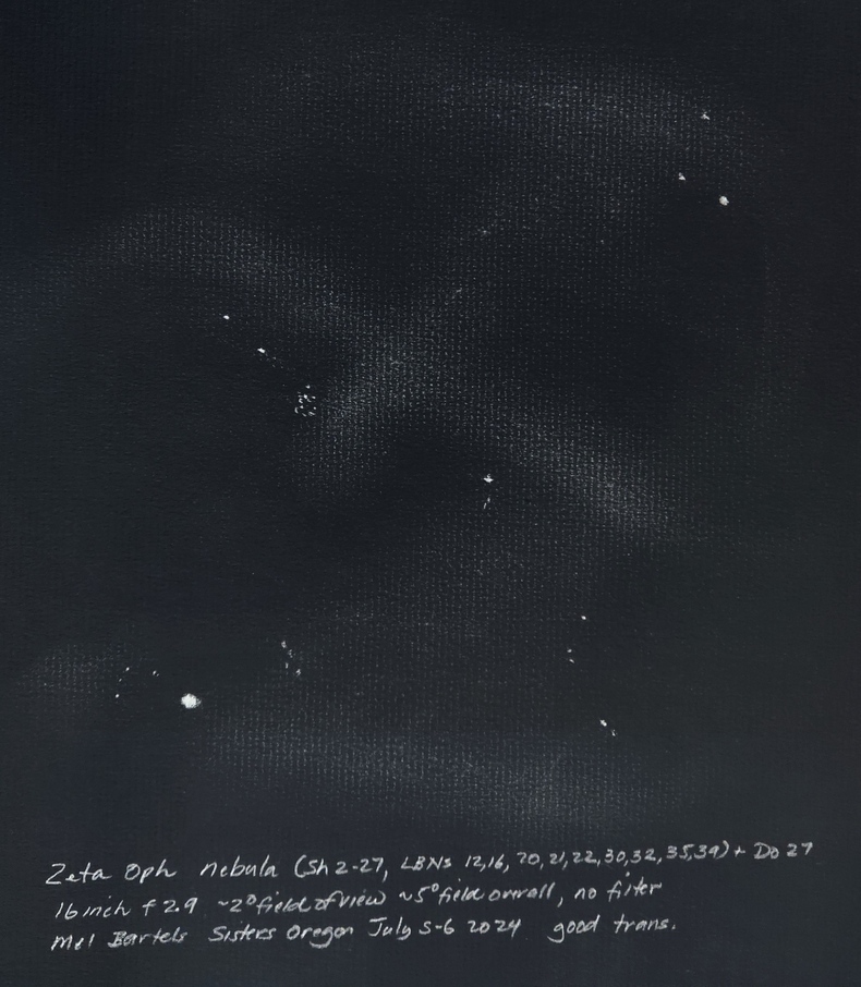
Zeta Oph nebula - Sh2-27.
Barnard's Galaxy, Ghost and IFN.

M57, extended ring, IFN

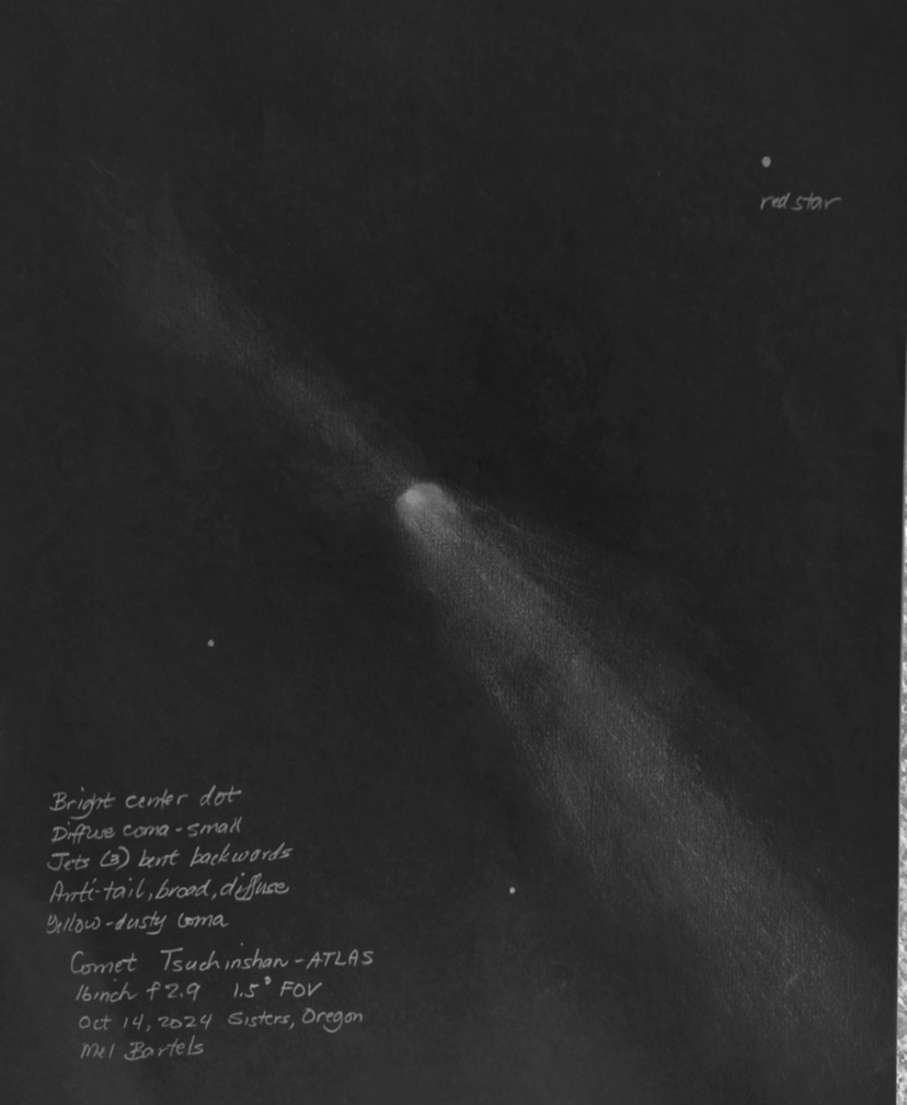
Comet Tsushinshan ATLAS 2024, Oct 14 2024, 16 inch f2.9
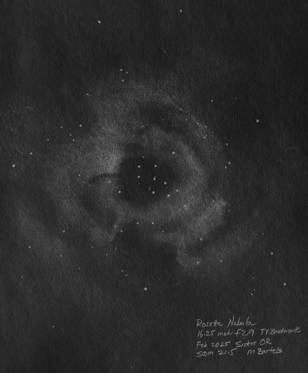
Rosette Nebula
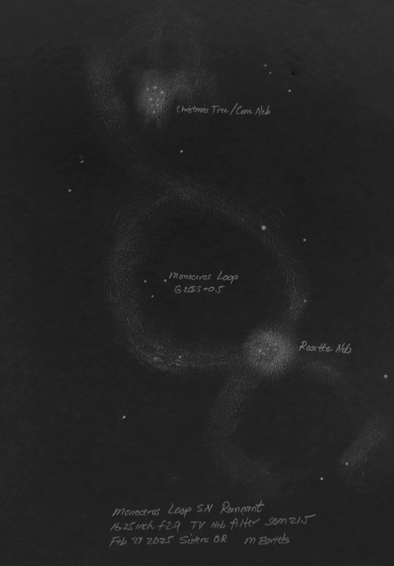
Monoceros Loop
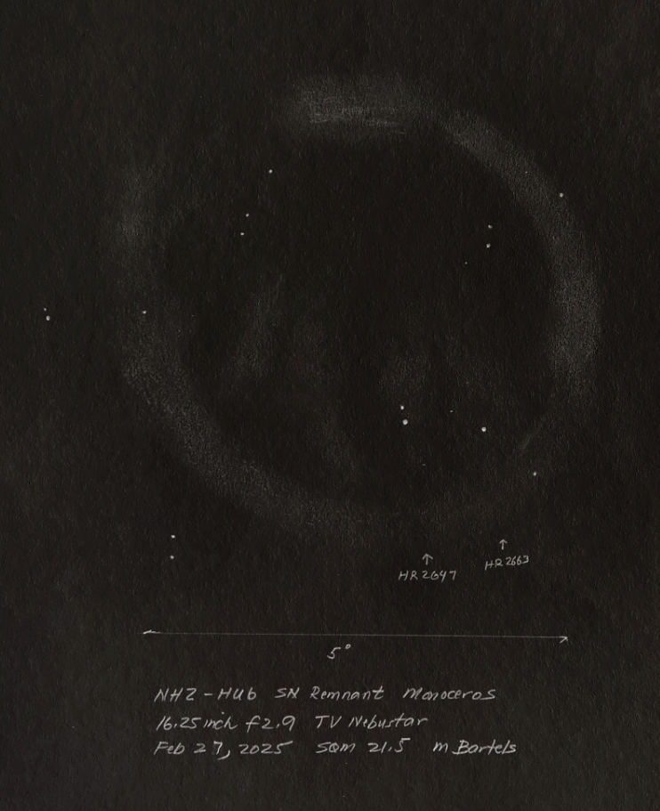
NHZ-HU6 loop
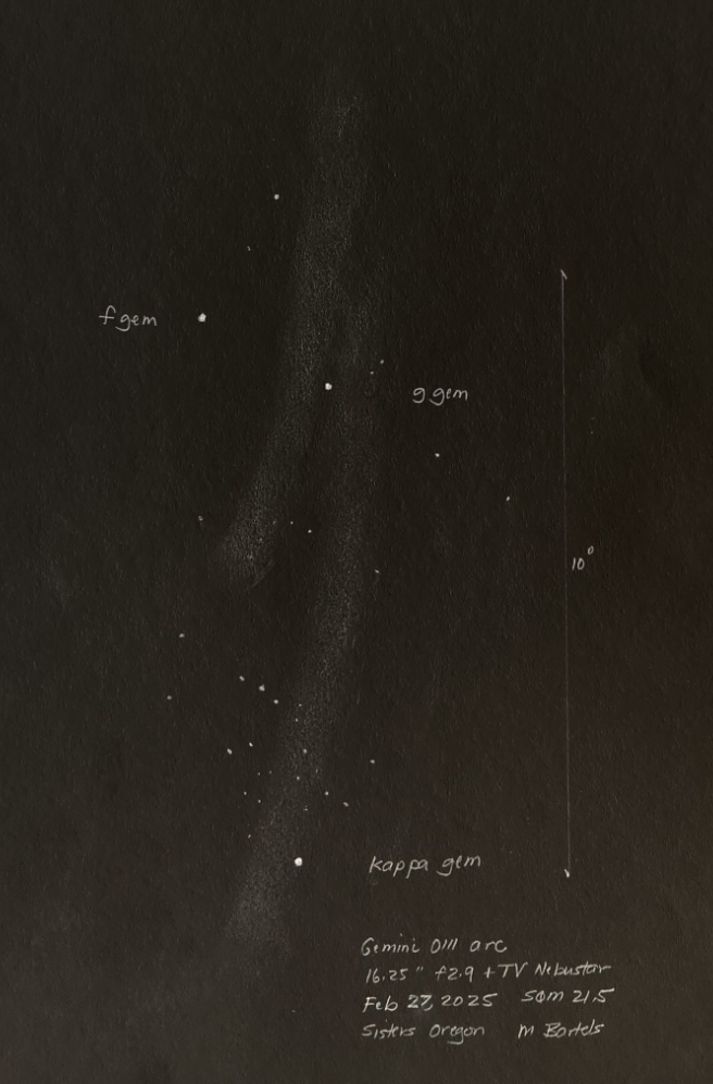
Gemini OIII arc
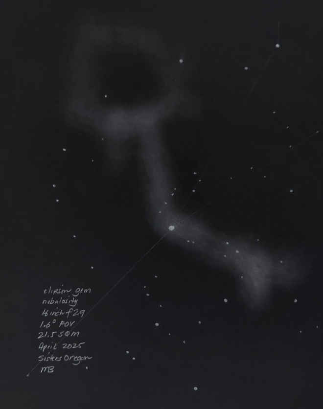
Epsilon Gem nebulosity
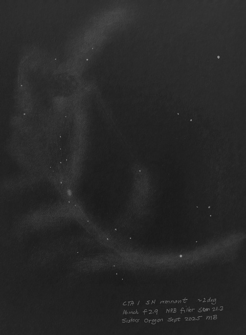
CTA1 supernova remnant
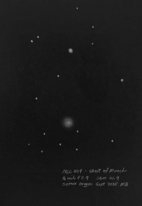
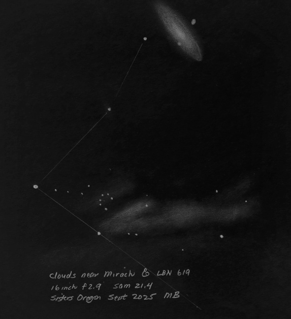
NGC 404 The Ghost of Mirach
IFN near Mirach
Andromeda Galaxy in OIII
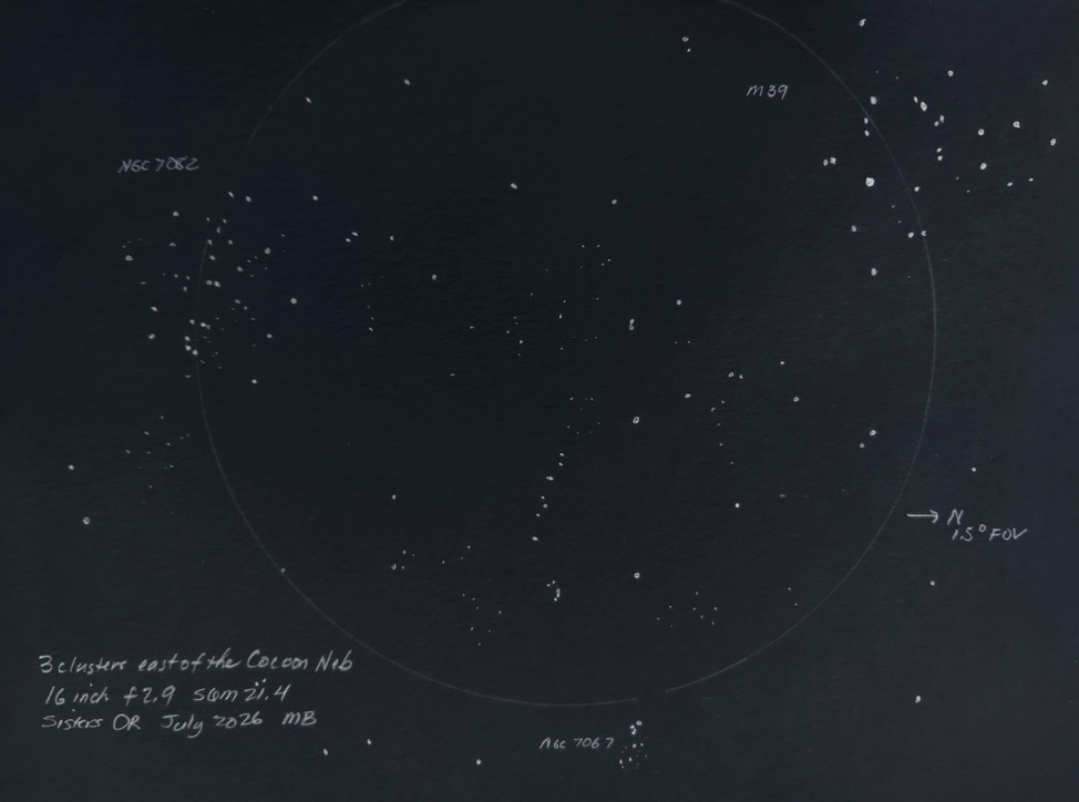
M39 NGC7082 NGC7067 east of the Cocoon Neb
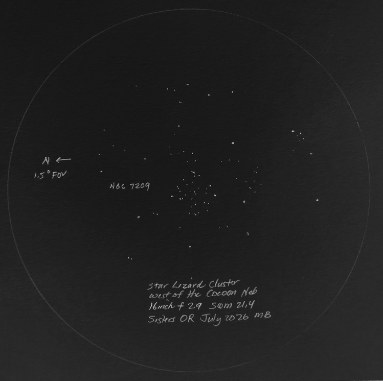
NGC 7209 west of the Cocoon Neb
Not only is the optical quality superb, but I am surprised as the 25 inch and 30 inch are quite sensitive to falling evening temperatures and need monitoring and fans.
List the good, the bad and the ugly as lessons to learn for the next telescope
The good:
The bad:
The ugly: